
JXHG-12/JXHG-24/JXHG-40.5
JXHG series outgoing feeder unit for downstream load distribution and branch protection.
Ключевые характеристики
Номинальное напряжение
12kV / 24kV / 40.5kV
Функция
Outgoing feeder
Protection
Relay protection ready
Применение
Utility / Industrial
Product Overview
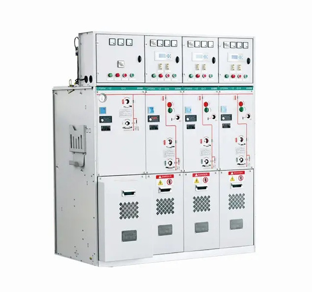
Our company can produce this product with a voltage class range of 1kV to 40.5kV and below. The fully enclosed and fully insulated gas-filled ring main unit is a metal common box type enclosed switchgear insulated by SF6 gas. This equipment can be composed of modules such as the load switch unit, the combined electrical appliance unit of load switch and fuse, the vacuum circuit breaker unit, and the busbar incoming line unit.
By adopting a series of excellent technologies and materials, it has excellent electrical and mechanical properties, is less affected by the environment and climate, is compact in size, easy to install, convenient to operate, maintenance-free, and has a flexible combination mode. The clear and intuitive design ensures simple and direct operation. It has a large feeder connection capacity and is suitable for a variety of wiring systems. Through this design, users can be provided with an integrated three-position load switch circuit breaker. Using a load switch instead of a disconnector is safer and more reliable. The fully enclosed design on the primary side provides protection against accidental contact, and the mechanical interlock live-line indicator that meets the five-prevention requirements can provide live-line indication for the incoming and outgoing lines.
Reliable operation: with a fully enclosed design, all switches and live busbar conductors are sealed in an air box welded by 3mm stainless steel plates; equipped with silicone rubber cable plugs to achieve full insulation and full sealing of the cable ends, thus not being affected by external environmental factors such as dust, humidity, and small animals. The spring energy storage operating mechanism can be operated manually or electrically. The simulated wiring diagram on the operation panel provides switch position indication. The cabinet body is made of galvanized steel plates and electrostatically sprayed on the surface to enhance corrosion resistance. The pressure gauge monitors the safe pressure range of SF6 gas in the box body. The main models of this product are JXHG-12, JXHG-24, and JXHG-40.5.
This product has the characteristics of being maintenance-free, highly reliable, with a service life of up to 20 years, having multiple incoming line methods, being able to achieve left, right, upper or front incoming lines, and multiple combination methods. Arbitrary combination can be achieved between each unit. Using insulated busbars, it can achieve front-to-back or left-to-right cabinet combination. The design scheme is flexible, the feeder outlet capacity is large, the floor space is small, and it is suitable for a variety of application requirements. It is mainly applicable to the power distribution networks of compact secondary substations, small industrial and mining enterprises, wind power plants, hotels, shopping malls, office buildings, commercial centers, and similar projects.
Enforce Standards
- GB 1984-2003 High Voltage AC Circuit Breaker
- GB 1985-2005 High Voltage AC Isolation Switch and Ground Switch
- GB 3804-2004 3.6kV to 40.5kV High Voltage AC Load Switch
- IEC 60265 High-Voltage Switches
- GB 16926-2009 AC High Voltage Load Switch Fuse Combination
- IEC 420 High-Voltage Alternating Current Switch-Fuse Combinations
- GB 3906-2006 3.6kV to 40.5kV AC Metal Enclosed Switchgear and Control Equipment
- IEC 62271 High-Voltage Switchgear and Controlgear
- GB/T 11022-2011 Common Technical Requirements for High Voltage Switchgear and Control Equipment
- IEC 60694 Common Specifications for High-Voltage Switchgear and Controlgear
- GB/T 11023 High Pressure Switchgear - Sulfur Hexafluoride Gas Seal Test Method
Normal Service Condition
- Maximum temperature: 40 degrees Celsius.
- Minimum temperature: -40 degrees Celsius.
- Maximum mean relative humidity: less than or equal to 95%.
- Altitude: less than or equal to 2000 meters.
Performance Parameter
Cell Code and General Parameters
| Cell Code | Significance |
|---|---|
| C | Standard single casing load switch unit |
| F | Load switch-fuse combined electrical unit |
| V | Circuit breaker unit |
| D | Cable entry unit without switch |
| + | Busbar side bushing |
| - | Busbar top sleeve |
| SL | Parent unit |
| M | Measuring unit |
| PT | PT cell |
| 1K2(4) | Load switch unit with double casing outlet |
| Performance Indication | Normal Operating Environment Conditions | ||
|---|---|---|---|
| SF6 Gas Pressure | The absolute pressure at 20C is 1.4bar | Maximum Temperature | 40C |
| Annual Leakage Rate of Gas | 0.2% / year | Minimum Temperature | -40C |
| Class of Protection | IP67 | Maximum Mean Relative Humidity | ≤95% |
| Air Chamber Stainless Steel Thickness | 3.0mm | Altitude | ≤2000 meter |
| Bus Bar | Meet the Criteria | ||
| Switchgear Inside the Bus | 400mm²Cu | GB/T11022, GB3906, GB1985 | |
| Switchgear Ground Bus | 150mm²Cu | GB16926, GB38041, GB1984 | |
| Colour | GB3309 | ||
| Switch Cabinet Front Panel | RAL7012 | IEC60056, IEC60129, IEC60265 | |
| Side Panel and Cable Room Front Cover Plate | RAL7035 | IEC60298, IEC60420, IEC60694 | |
Module Performance Parameter
| Item | C Module | F Module | V Module | V Module | CB Module | CB Module |
|---|---|---|---|---|---|---|
| Load Switch | Combination Apparatus | Vacuum Switch | Isolation / Ground Switch | Vacuum Circuit Breaker | Isolation / Ground Switch | |
| Rated Voltage kV | 12 | 12 | 12 | 12 | 12 | 12 |
| Rated Frequency Hz | 50 | 50 | 50 | 50 | 50 | 50 |
| Power Frequency Withstand Voltage (Phase / Port) kV | 42/48 | 42/48 | 42/48 | 42/48 | 42/48 | 42/48 |
| Lightning Impulse Withstand Voltage kV | 75/85 | 75/85 | 75/85 | 75/85 | 75/85 | 75/85 |
| Rated Current A | 630 | note | 630 | 1250/630 | ||
| Rated Closed-Loop Breaking Current A | 630 | |||||
| Rated Cable Charging Breaking Current A | 135/135 | |||||
| Rated Short Circuit Closing Current (Peak) | 50 | 80 | ||||
| Rated Peak Withstand Current kA | 50 | |||||
| Rated Short-Time Withstand Current kA / 3s | 20 | |||||
| Rated Short Circuit Breaking Current kA | 31.5 | 20 | 25 | 25 | ||
| Rated Transfer Current A | 1750 | |||||
| Fuse Maximum Current A | - | 125 | ||||
| Loop Resistance Ω | ≤300 | ≤600 | ||||
| Mechanical Life (second) | 5000 | 3000 | 5000 | 2000 | 5000 | 5000 |
Связанные модели в категории Средневольтные КРУ
Назад к категории Средневольтные КРУ или свяжитесь с нами для получения даташитов и коммерческого предложения.