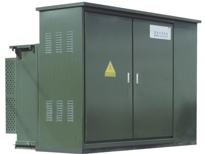
American-style substation
Pad-mounted American-style compact substation with integrated transformer and low-voltage outgoing section.
Quick Specifications
Voltage Class
10kV / 0.4kV
Max Operating Voltage
12kV
Rated Capacity
100 to 1250kVA
Structure
Pad-mounted
Product Overview
The box transformer substations in China were initially developed from the European-style box transformer substations, and they are often relatively bulky in size.
With the opening of China's foreign economy and the vigorous development of the market economy, around the 1990s, the American COOPER Company took the lead in introducing American-style box transformer substations into the Chinese market, and they achieved rapid development in the Chinese market with their unique characteristics.
From south to north and from east to west in China, the American-style box transformer substations can be seen almost everywhere, and most of them are products copied by domestic manufacturers, and the quality of these products can be said to vary widely.
Through years of application and practice, it is necessary to conduct a serious analysis of the American-style box transformer substations in combination with China's national conditions, and give them a correct positioning, so as to promote the technological and market development of box transformer substations in China.
Our company can produce this product with a voltage class of 40.5kV and below.
Enforce Standards
- GB 1094.1-2013: Power transformers
- GB/T 11022-2011: Common technical conditions for high-voltage switchgear and controlgear standards
- GB 7251.1-2013: Low-voltage switchgear and controlgear assemblies
- JG/T 10217-2013: Pad-mounted transformer
Normal Service Condition
- It is used outdoors, and the specific operating conditions are related to the required operating environment of the transformers and switchgear it contains.
Performance Parameters
General Technical Parameter Table
| Item | Side / Description | Unit | Technical Parameter |
|---|---|---|---|
| Rated Voltage | High pressure side | kV | 10 |
| Low pressure side | kV | 0.4 | |
| Maximum Operating Voltage | kV | 12 | |
| Rated Frequency | Hz | 50 | |
| Rated Capacity | kVA | 100, 125, 160, 200, 250, 315, 400, 500, 630, 800, 1000, 1250 | |
| 1 Minute Power Frequency Withstand Voltage | kV | 35 | |
| Lightning Impulse Withstand Voltage | kV | 95 | |
| No-Load Voltage Regulation | 10kV +/- 2 x 2.5% | ||
| Ambient Temperature | deg C | -45 to 40 | |
| Allowable Temperature Rise | deg C | 65 |
Loss and Impedance Parameter Table
| Capacity (kVA) | High Tension (kV) | Tapping Range (%) | Low Pressure (kV) | Coupling Group | No-Load Loss (W) | Load Loss (W) | No-Load Current (%) | 10kV Impedance (%) | 20kV Impedance (%) |
|---|---|---|---|---|---|---|---|---|---|
| 100 | 20 or 10 | +/- 2 x 2.5 | 0.4 | Dyn-11 / Yyn-0 | 200 | 1500 | 1.6 | 4.5 | 5.5 |
| 125 | 240 | 1800 | 1.5 | ||||||
| 160 | 280 | 2200 | 1.4 | ||||||
| 200 | 340 | 2600 | 1.3 | ||||||
| 250 | 400 | 3050 | 1.2 | ||||||
| 315 | 480 | 3650 | 1.1 | ||||||
| 400 | 570 | 4300 | 1 | ||||||
| 500 | 680 | 5100 | 1 | ||||||
| 630 | 810 | 6200 | 0.9 | 6 | |||||
| 800 | 980 | 7500 | 0.8 | ||||||
| 1000 | 1150 | 10300 | 0.7 | ||||||
| 1250 | 1360 | 12000 | 0.7 |
Related Models in Substations
Back to Substations or contact us for datasheets and quotations.