GCS
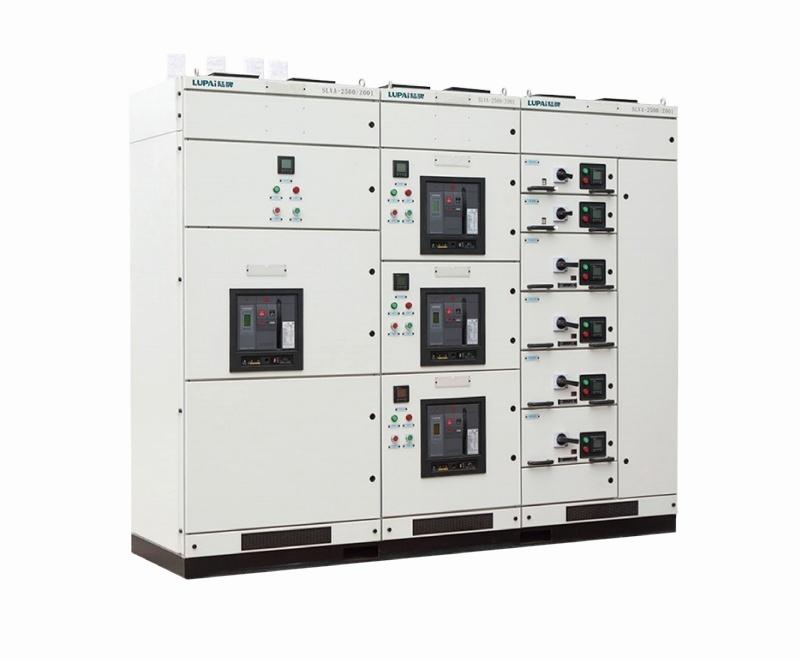
GCS low-voltage withdrawable switchgear for centralized motor control, reactive power compensation, and industrial distribution systems up to 6300A.
Quick Specifications
Main Circuit Voltage
1kV and below
Rated Current
Up to 6300A
Cabinet Type
Withdrawable
Standards
IEC 439 / GB 7251
Product Overview
The GCS low-voltage withdrawable switchgear is applicable to the power distribution systems of industries such as power plants, petroleum, chemical engineering, metallurgy, textile, and high-rise buildings.
In places with high automation requirements such as large-scale power plants and petrochemical systems, which require interfaces with computers, it serves as a low-voltage complete power distribution device for the centralized control of distribution motors and reactive power compensation in power generation and power supply systems with a three-phase alternating current frequency of 50(60)Hz, a rated working voltage of less than 1kV, and a rated current of 6300A or less.
Enforce Standards
- IEC 439: Low-voltage switchgear and control equipment
- GB 7251: Low-voltage switchgear
Normal Service Condition
- The ambient air temperature shall not be higher than +40 degrees Celsius and not lower than -5 degrees Celsius, and the average temperature within 24 hours shall not be higher than +35 degrees Celsius. When these limits are exceeded, the capacity shall be derated for operation according to the actual situation.
- It is for indoor use, and the altitude of the installation location shall not exceed 2000 meters.
- The relative humidity of the ambient air shall not exceed 50% when the maximum temperature is +40 degrees Celsius. At lower temperatures, a higher relative humidity is allowed. For example, it is 90% at +20 degrees Celsius. The influence of occasional condensation caused by temperature changes should be taken into account.
- When the device is installed, the inclination from the vertical plane shall not exceed 5 degrees, and the entire group of cabinet rows shall be relatively flat.
- The device shall be installed in a place without severe vibration and impact, and where the electrical components will not be subject to undue corrosion.
Performance Parameter
| Serial Number | Item | Sub Item | Argument |
|---|---|---|---|
| 1 | Main circuit rated voltage (V) | 1kV and below | |
| 2 | Rated voltage of auxiliary circuit | AC 220, 380(400), DC 110, 220 | |
| 3 | Rated frequency (Hz) | 50(60) | |
| 4 | Rated insulation voltage (V) | 660 | |
| 5 | Rated current (A) | Horizontal bus | <=6300 |
| Rated current (A) | Vertical bus (MCC) | 1000 | |
| 6 | Bus rated short-time withstand current (kA/1s) | 50, 80 | |
| 7 | Bus rated peak withstand current (kA/0.1s) | 105, 176 | |
| 8 | Power frequency test voltage (V/1min) | Main circuit | 2500 |
| Power frequency test voltage (V/1min) | Auxiliary circuit | 2000 | |
| 9 | Bus bar | Three-phase four-wire system | A.B.C.PEN |
| Bus bar | Three-phase five-wire system | A.B.C.PE.N | |
| 10 | Class of protection | IP30, IP40 |
Size (mm)
| Option 1 | Option 2 | Option 3 | Option 4 | |
|---|---|---|---|---|
| Cabinet height (H) | 2200 | |||
| Cabinet width (D) | 400 | 600 | 800 | 1000 |
| Tank depth (W) | 800, 1000 | 800, 1000 | 600, 800, 1000 | 600, 800, 1000 |
| Cabinet Width (D) | Tank Depth (W) | Cabinet Height (H) |
|---|---|---|
| 600, 800, 1000 | 800, 1000 | 2200 |
| Serial Number | Name | Condition | Tolerance (mm) |
|---|---|---|---|
| 1 | Perpendicularity | 3.3 | |
| 2 | Levelness | Top of two cabinets next to each other | 2 |
| Levelness | Top of a row cabinet | 5 | |
| 3 | Unevenness | Two cabinets next to each other | 1 |
| Unevenness | Lining the sides of the cabinets | 5 | |
| 4 | Cabinet joint | 2 |
Back to Low Voltage Switchgear or contact us for datasheets and quotations.