Select the ratio from the feeder, then check each core
A current transformer specification needs more than a ratio. Start with the expected operating current and maximum continuous duty, then identify which secondary cores serve metering, overcurrent protection, differential protection, or other functions. The relay and meter requirements determine the rest of the schedule. A cabinet's busbar current rating is not automatically the correct CT primary rating for every outgoing feeder.
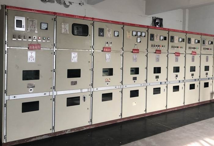
This guide concerns CTs integrated into a medium-voltage switchgear assembly. It does not establish a standalone Jinxing CT catalogue or confirm availability of a particular ratio. Ask for the CT schedule with the proposed panel drawings.
Use a calculation as an input, not a final specification
For a balanced three-phase transformer feeder, rated line current can be estimated as kVA divided by the product of the square root of three and line-to-line kV. As an illustration, a 1,000 kVA transformer on an 11 kV feeder has a rated primary current of about 52.5 A. This example describes a hypothetical load, not a Jinxing product rating.
That calculation does not by itself select a 75/1, 100/1, or any other CT. The designer still needs overload allowance, future loading, the minimum current that must be measured reliably, available ratios, relay settings, fault current and utility metering rules. Oversizing a ratio merely to leave room for expansion can reduce the useful secondary signal at today's low load. Conversely, ignoring future continuous duty can require replacement later.
Put the missing information into a core schedule
| Schedule field | Procurement decision it supports |
|---|---|
| Primary and secondary current | Match feeder duty and the meter or relay input |
| Core identification and function | Keep protection and billing requirements explicit |
| Accuracy specification and rated burden | Establish the conditions under which accuracy is claimed |
| Connected devices and secondary cable route | Check the actual burden, including wiring |
| Fault level and protection requirements | Let the protection engineer assess saturation and transient duty |
| Insulation, dimensions and mounting | Confirm suitability inside the proposed compartment |
| Terminal marking and test facilities | Support correct wiring, commissioning and maintenance |
Do not replace a detailed protection-core requirement with a generic metering accuracy number. The protection study may call for additional excitation or transient information. Have the responsible engineer approve those requirements before ordering the assembly.
Check the entire secondary circuit
Secondary burden includes both connected instruments and cable losses. A longer route to a remote relay room can change the result even when the CT and relay models remain unchanged. Confirm cable length, conductor size, connections and the device manufacturer's input burden.
A 1 A circuit can reduce cable losses compared with a 5 A circuit of the same resistance, because resistive loss follows current squared. It is not a drop-in substitution: the CT, relay, meter, terminal drawings and settings must agree. Ask the supplier to identify the complete secondary circuit being evaluated rather than quoting an isolated VA value.
CT secondary work requires an approved safe procedure. Do not open an energized current-transformer secondary circuit. Specify suitable test and shorting arrangements for the maintenance method; this article is a procurement checklist, not an instruction to perform live work.
Send a panel-specific request
- Identify the incoming or outgoing feeder and its normal, maximum and expected future current.
- Supply the single-line diagram, fault study and relay or meter input requirements.
- List the required cores separately, including utility-owned metering where applicable.
- Give the secondary cable route and the party responsible for the burden calculation.
- Request the CT data sheet, terminal diagram, approved core schedule and applicable test evidence with the panel quotation.
Review the KYN switchgear family where its panel arrangement suits the project, then send the feeder requirements. A useful quotation should state which assumptions remain open and who approves them.
Technical reference
Current-transformer burden and secondary wiring losses explains why connected devices and wiring must both be included. Its general circuit guidance does not certify a Jinxing assembly or replace the project's protection study.