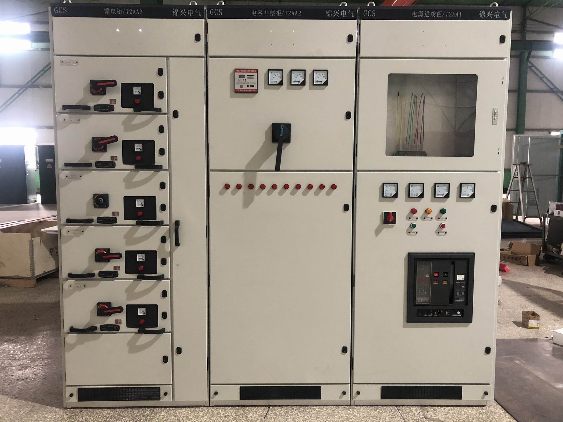
Freeze the cable termination arrangement before approving LV panel dimensions. Rated current and enclosure width do not establish whether the specified cables can be routed, supported and connected correctly. A practical RFQ combines the cable schedule with a dimensioned termination drawing and the installation contractor's entry arrangement.
Start from the cables that will actually arrive
List conductor material, number of parallel runs, number of cores, insulation construction and outside diameter for each significant feeder. Include the selected terminal or lug arrangement if it has already been designed. A description such as “large incoming cable” leaves too much for the panel builder to infer.
Ask the cable supplier for the applicable bending and installation constraints. These vary with construction and handling condition. Do not replace that information with a generic clearance copied from another panel project. The assembly supplier then needs to show how the proposed connection accommodates the specified cables.
| Cable interface | Drawing information required | Purchasing risk if omitted |
|---|---|---|
| Entry from a floor trench | Opening position, gland plate and support elevation | The civil opening may not align with the cabinet |
| Overhead entry | Top opening, access and cable support | Roof space may be consumed by other equipment |
| Parallel single-core runs | Terminal positions and approved conductor arrangement | Connections may need unplanned adapters or extensions |
| Neutral and protective conductors | Separate termination positions and accessibility | Main phase connections can hide missing interfaces |
| Future outgoing circuits | Reserved entry area and terminal provision | An empty compartment may still be impossible to cable |
Compare layout rather than cabinet volume
A deeper enclosure may offer more routing room, but its internal arrangement still matters. A terminal located behind another device can be difficult to access even when the overall cabinet is large. Request sections or detailed views for the incomer and the largest outgoing circuits, not only the external general arrangement.
The drawing should distinguish space for bending, space for cable support and access needed to complete the connection using the specified components. It should also show how partitions and removable covers affect that access. Required working clearances outside the board belong in the room-layout review, alongside the internal connection space.
Example: parallel incoming cables change the offer
Consider an illustrative incomer initially quoted on the assumption of one cable run per phase. The installation designer later chooses two parallel runs. Even if the main electrical rating is unchanged, the terminal arrangement, gland plate and support provisions may need revision.
The buyer should issue the updated cable schedule and ask for a revised termination drawing before production. Request written confirmation of the accepted lug or connector arrangement. A last-minute instruction to “make both cables fit” transfers a design interface problem to the installer without resolving it.
Include environmental and material interfaces
Where the board requires a particular ingress protection level, agree the entry components and who supplies them. Openings added on site can affect the intended enclosure arrangement. For single-core power cables, ask the designer and supplier to review the entry-plate and conductor grouping details appropriate to the installation.
If aluminium conductors are specified, identify compatible terminations and the approved connection system. The procurement package should name the required interface and documentation, rather than treating conductor material as a minor substitution after the board has been built.
Set an acceptance point before manufacture
IEC 60364-5-52 addresses wiring-system selection and electrical connections. Use the applicable installation requirements together with the assembly specification, cable data and supplier instructions. No universal minimum cable compartment dimension can be inferred from an LV cabinet model name.
Ask the LV panel supplier to return a marked cable-interface schedule with the quotation. Have the installation contractor confirm the trench or overhead approach and the selected terminations. Release the cabinet dimensions only when these interfaces agree; this is cheaper than redesigning a delivered board around cables that were never included in its layout review.