Quick answer
A nominal control voltage is only one input to the auxiliary-power design. Ask for a duty schedule identifying continuous loads, short-duration operating demands and functions required during loss of the normal supply. Allocate the source, distribution and equipment terminals to named suppliers before comparing quotations.
Begin with functions that must remain available
The protection engineer and owner should define the required response to loss of auxiliary power, including which protection, tripping, indication and communications functions remain available. Do not select a battery or transformer solely from the number of panels.
Manufacturer instructions demonstrate that control supply availability is part of equipment acceptance: Schneider Electric's Masterclad start-up material refers to order-specific battery connections and verification of trip voltage at the equipment. The relevant procedure for a purchased panel must come from its own manufacturer. Masterclad control-power verification.
Build a duty schedule from actual components
| Load group | Data to obtain | Why the timing matters |
|---|---|---|
| Protection and indication | Continuous demand and permitted supply range | Establishes the standing auxiliary load |
| Trip and close circuits | Device demand, duration and required operating duty | Determines short-duration source capability |
| Charging motors | Starting and running demand; expected sequence | May create peaks different from steady consumption |
| RTU and communications | Continuous load and required backup period | Extends the duty beyond switchgear mechanisms |
| Heaters and other services | Voltage and operating arrangement | May belong to a separate auxiliary supply |
Use the actual proposed component data. Identify whether demands are coincident, sequential or mutually exclusive under the approved design. The supplier should state assumptions so the engineer can check them against the operating philosophy.
Distinguish autonomy from operating capability
A source that supports low steady demand for an extended period may still require review for short operating peaks. Conversely, a source that can deliver a short pulse does not establish how long protection and communications remain supplied.
Ask the designer to review the required autonomy, device terminal conditions, distribution losses and applicable environmental or ageing allowances. No generic ampere-hour value can substitute for the load schedule and the selected source characteristics. Record the agreed calculation basis with the equipment documents.
Example: SCADA is added after the battery is ordered
In a hypothetical project, the initial auxiliary schedule covers relays and breaker mechanisms. A later integration package adds a gateway, network equipment and continuous monitoring. These devices look small compared with the primary switchgear, but their sustained demand changes the backup duty.
Before accepting the addition, update the schedule and ask the responsible designer to check the source and distribution. Also confirm who supplies any voltage conversion and whether new alarms must be brought into the control system. Treat the change as a defined interface revision rather than an unrecorded connection to a spare terminal.
Decide who owns loss-of-supply behaviour
The order should identify which party provides charger-failure indication, low-supply alarms and any required monitoring interface. Agree how the receiving system represents unavailable data and which responses are implemented locally. These decisions belong in the approved control philosophy and acceptance plan.
Separate factory verification of panel wiring from site verification of the complete auxiliary system. A factory test using a temporary source does not by itself accept the installed battery, charger and cable distribution.
Inputs for a control-power quotation
For a medium-voltage switchgear package, send the preferred auxiliary system, panel and component schedule, required backup duty, communications loads and available site supplies.
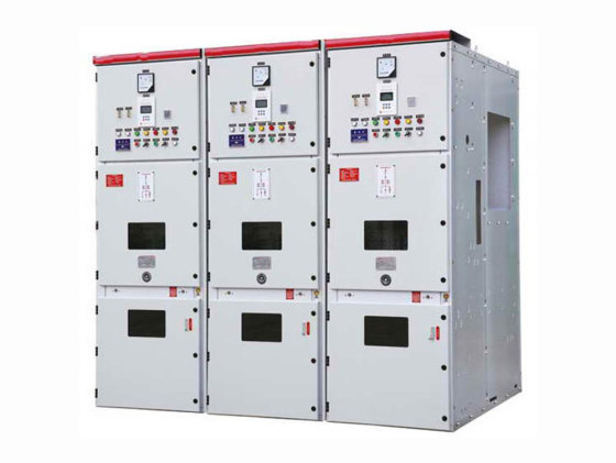
Through the project enquiry page, request a load schedule and clear source-to-terminal scope for the proposed KYN28-12 configuration. Device ratings, source sizing and included auxiliary equipment require project-specific technical confirmation.