Establish what the requested package contains
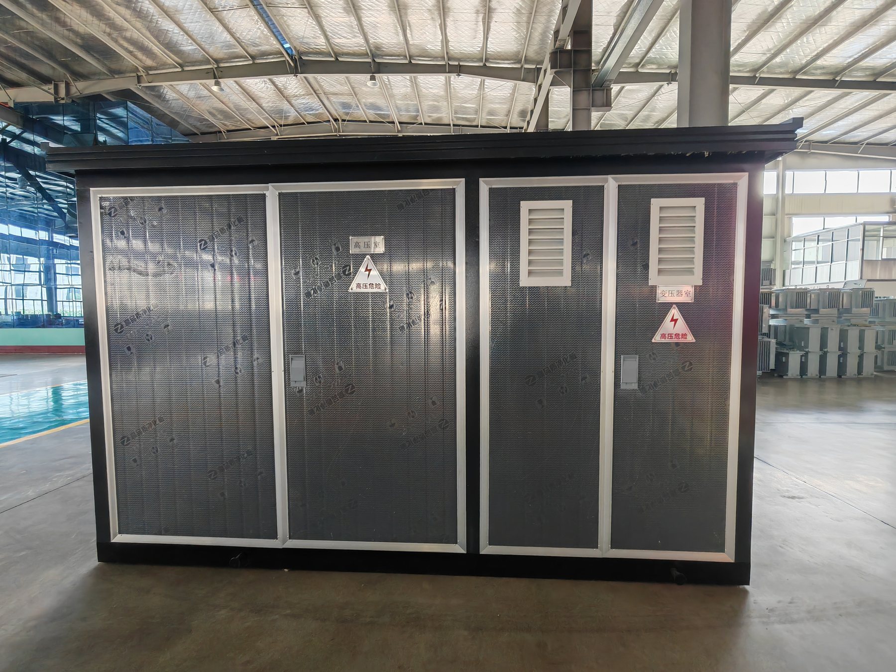
A pad-mounted transformer and a compact substation can perform related distribution functions while having different equipment boundaries. The first may place transformer terminals and switching accessories in an integral compartment. A complete substation package may include separate medium-voltage switching and low-voltage distribution sections.
Begin with the utility connection drawing and an equipment boundary diagram. Identify who supplies the MV switching, transformer protection, metering, LV main device, outgoing circuits and enclosure. Avoid equating an “American-style” product label with a particular utility-approved dead-front or loop-feed construction.
Jinxing's published substation pages are a starting point for project review. They do not independently verify every pad-mounted terminal system, switching arrangement or regional approval. Obtain a drawing and explicit configuration confirmation before treating a proposed product as equivalent.
Describe interfaces before selecting a footprint
| Decision | Alternatives to identify | Why the distinction matters |
|---|---|---|
| Supply topology | Radial connection or a defined loop arrangement | Determines cable interfaces and the intended switching scheme |
| MV termination | Specified live-front or separable-connector arrangement | Changes compartment geometry and operating requirements |
| Protection location | Integrated transformer accessories or separate MV section | Defines equipment ownership and coordination inputs |
| LV connection | Cable terminals, bus connection or distribution board interface | Controls termination space and the delivery boundary |
| Access arrangement | Required door sides, locks and operating space | Affects the civil pad and utility access |
| Metering location | MV, LV or an external approved metering assembly | Changes wiring, compartments and approval responsibilities |
A connector voltage designation is not a complete interface definition. The project needs the applicable interface standard, current duty, cable construction and mating accessory identification. Compatibility must be established from the actual drawings.
Example: a campus with a loop cable route
Consider a campus whose drawing shows two MV cables entering a transformer position. That fact alone does not establish that the transformer needs two independently switched loadbreak ways. The utility may require loop continuity through a separate RMU, or it may specify an integral switching arrangement.
Ask the designer to identify the normal open point, switching ownership and isolation boundaries. Then compare offers against that agreed scheme. Ordering from the number of cables alone can result in the wrong terminal arrangement even when the voltage and kVA are correct.
Review the pad after the equipment arrangement
The structural designer needs the confirmed footprint, loaded mass, lifting and handling information, cable opening positions and anchoring requirements. Preliminary catalogue dimensions should not become construction dimensions without approval.
Check cable bending and connector access below and inside the compartment. Also review drainage, vehicle impact exposure and access to doors. These civil and access decisions need coordination with the owner; the transformer supplier's enclosure drawing cannot settle the entire site approval.
Make the quotation scope auditable
Request an equipment list with each switch, protective function, meter interface and LV connection identified as included, excluded or subject to review. Ask which drawings and test records will refer to the exact offered assembly. A test document for a transformer does not by itself establish the suitability of the complete substation enclosure.
Send the utility drawing, nominal system information, required kVA, cable schedule and ownership boundary through project enquiries. Compare the compact substation family and American compact substation page as candidate configurations, with pad-mounted construction and approval requirements explicitly awaiting project confirmation.