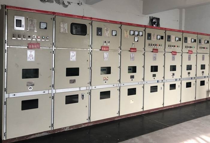
One ratio can conceal two different jobs
A current transformer supplies a scaled current signal, but the purpose of that signal determines the required performance. A billing meter needs its specified accuracy over the relevant load range. A protection relay needs suitable current reproduction under the fault conditions used by its protection functions.
Consequently, a metering accuracy label is not a substitute for a protection-core specification. A CT assembly can contain separate cores serving these duties, but the number, available characteristics and space must be confirmed for the proposed switchgear configuration. This guide addresses CT selection within a complete panel; it is not an offer of standalone CT supply.
Compare the duty of each core
| Review point | Metering core | Protection core |
|---|---|---|
| Primary purpose | Measure operating current for an instrument or meter | Deliver the signal required for fault detection |
| Accuracy basis | Applicable measuring class and operating current range | Protection class or relay-specific excitation requirements |
| High-current behavior | Instrument security and specified saturation characteristics matter | Saturation must be assessed against protection performance |
| Connected circuit | Meter inputs, test facilities and secondary leads | Relay inputs, leads and any interposing devices |
| Approval owner | Metering authority or project instrumentation designer | Protection engineer and relay application requirements |
The relevant standard definitions and device documentation determine the final selection. Avoid deciding that one core is “better” simply because its class number appears smaller.
Calculate the actual secondary burden
The CT burden includes the connected equipment and secondary circuit resistance. For the same circuit resistance, the lead burden follows current squared times resistance. A hypothetical two-ohm secondary loop contributes 2 VA at 1 A and 50 VA at 5 A. These are arithmetic examples, not suggested design burdens.
That difference makes lead length important, especially when instruments are remote from the cabinet. It does not mean every application should change to 1 A: the relay or meter input rating and existing interfaces must also match. Request the complete burden calculation, not just the CT's nominal VA label.
Example: identical ratios, unsuitable substitution
Suppose a panel drawing calls for separate 400/1 A metering and protection cores. A substitution offered with the same ratio may still lack the protection characteristic required by the selected relay. Conversely, using an unspecified protection core for billing does not establish revenue-metering accuracy.
The review should compare the core schedule, connected devices and the protection calculation. If a relay model changes, revisit its CT requirements before approving the substitution. Preserve core numbers and terminal labels so the installation team can identify which circuit serves each duty.
Information that belongs on the panel schedule
- Continuous and maximum operating primary current, with future load expectations.
- Available fault current and the protection functions being applied.
- Ratio, secondary current and dedicated purpose of every core.
- Required measuring or protection characteristics and connected burden.
- Lead lengths, meter or relay input data, test-terminal arrangement and earthing details.
Secondary circuits require equipment-specific safe working procedures. In particular, CT secondary circuits must not be opened while primary current flows. The commissioning plan should verify ratio, polarity, core identity and the restoration of test connections under approved conditions.
For an assembled solution, use medium-voltage switchgear and the KYN28 cabinet page to identify the panel context. Send the CT schedule and relay requirements through project enquiries; final core performance and installation compatibility need configuration-specific confirmation.