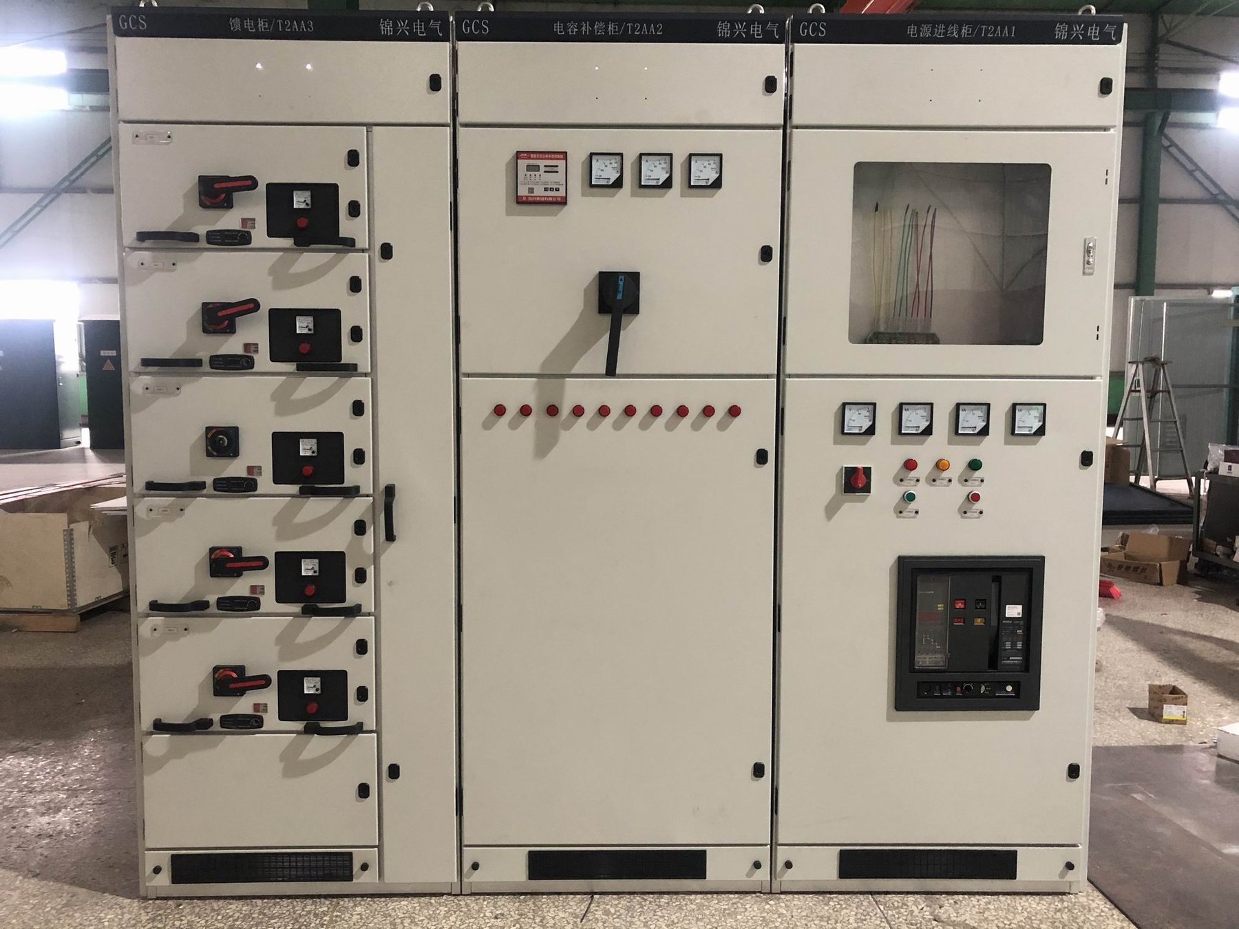
Size the correction around the operating profile
The transformer nameplate is not enough to size a compensation cabinet. A plant may draw high reactive power during production and very little overnight. A fixed bank chosen for the busiest hour can leave the installation overcompensated at light load.
Collect interval measurements covering representative production, idle and standby periods. Identify where the meter measures power and whether the recorded power factor is displacement or true power factor. Capacitors address reactive demand at the fundamental frequency; a poor power factor caused substantially by distortion requires a different assessment.
Turn measurements into a cabinet requirement
| Operating condition | Information needed | Cabinet decision |
|---|---|---|
| Stable base production | Persistent reactive demand | Whether a fixed portion is appropriate |
| Several production lines cycling | Size and duration of reactive changes | Number and size of automatic stages |
| Rapidly changing process | Required response and switching frequency | Switching technology and controller review |
| Overnight or weekend operation | Minimum load and remaining reactive demand | Smallest effective stage and overcompensation prevention |
| Generator supply | Approved operating limits and transfer sequence | Inhibit, disconnect or separately reviewed control mode |
| Nonlinear equipment present | Harmonic measurements and network information | Suitability of the proposed bank architecture |
Do not infer an acceptable harmonic configuration from kvar alone. When requesting a compensation arrangement within low-voltage switchgear, provide the harmonic measurements and source operating modes for a separate assessment of any proposed capacitor-reactor combination.
A preliminary calculation with explicit limits
For a sinusoidal illustrative load of 300 kW, improving displacement power factor from 0.80 to 0.95 gives approximately:
Qc = P × [tan(arccos(0.80)) − tan(arccos(0.95))] = 126 kvar.
This estimates the correction at that operating point. It does not specify a complete cabinet, a universal stage combination or a guaranteed billing saving. Repeat the calculation across the measured load profile, then choose a practical arrangement subject to the actual equipment offer.
For example, a single stage close to the entire calculated value cannot follow small overnight demand changes. More stages may improve resolution, but their sizes and switching duty must be considered together. Ask the supplier to explain how the proposed arrangement responds to the supplied demand record.
Check sensing and control boundaries
The controller must observe the part of the network being compensated. Show the sensing CT position, phase association and capacitor connection on the single-line diagram. A bank may be physically installed beside a main board while its measurement point excludes part of the intended load.
Where multiple incomers or a bus coupler change the electrical arrangement, describe each operating state. The control design must account for those states; specifying one CT ratio without the switching topology leaves an important assumption unresolved.
Compare the complete offered assembly
Request a stage schedule identifying nominal kvar, switching devices, protection, ventilation and controller functions. Include discharge arrangements and maintenance access in the equipment review, without treating a generic delay value as an operating instruction. The operating manual must define the selected assembly's safe isolation and re-energization requirements.
Provide measured power data, tariff objective, system voltage, fault level, generator arrangement, harmonics and ambient conditions through project enquiries. Review the low-voltage switchgear family as the assembly context. Capacitors, controllers and reactors are discussed here as configured components of a cabinet; their separate supply is not established by this guide.