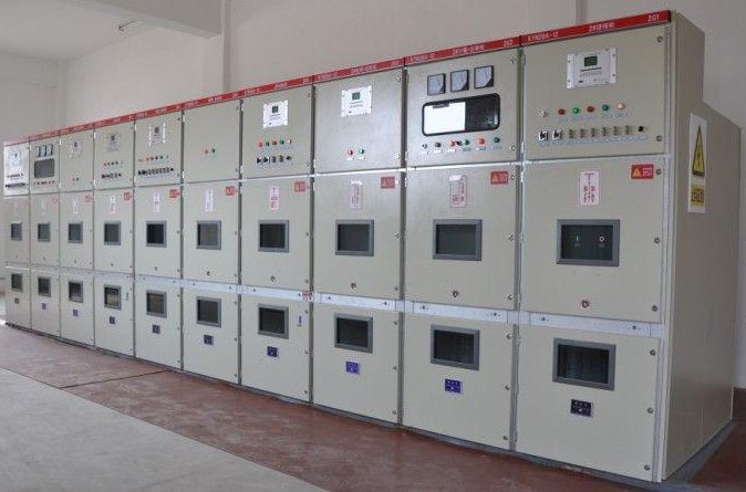
Select an extensible RMU when the project has a credible need for additional connected functions and can preserve the required expansion interface. A non-extensible arrangement may suit a stable, defined network. The comparison should consider the future connection method, room layout and operating interruption, rather than treating extensibility as an unspecified spare panel position.
Define what expansion means for this project
Write down the expected future function: another transformer feeder, an additional ring connection, metering or a different protection arrangement. Record the likely timing and whether the present project has approved that expansion or merely considers it possible. These distinctions help compare a firm provision with an expensive but uncertain option.
An empty space beside an RMU is useful only if the chosen equipment can connect there in the intended manner. Conversely, a compatible busbar extension arrangement still needs physical installation access, cable routes and sufficient room. Electrical compatibility and civil provision must be evaluated together.
| Future requirement | Provision to confirm now | Evidence requested from supplier |
|---|---|---|
| Additional feeder on one side | Available and protected extension interface | Interface drawing and compatible functional units |
| Additional transformer capacity | Appropriate new feeder and protection review | Permitted arrangement and reassessment requirements |
| Later building phase | Floor space, cable route and installation access | Overall dimensions including future sections |
| Possible product revision | Continued interface compatibility | Written scope of compatibility and support assumptions |
| Limited outage availability | Connection and commissioning constraints | Documented installation requirements and outage scope |
Identify the extension structure before the first order
Request a section drawing showing whether future functions connect through an external bus interface, another complete assembly, or another manufacturer-defined arrangement. Mark the interface location and every option that must be fitted in the initial order. Adding a function within a common enclosure and connecting another enclosure are different construction proposals.
A manufacturer's illustrated side-extension arrangement shows optional bushings and dedicated connection accessories. This historical ABB example demonstrates an interface-specific design; its ratings and compatibility do not apply to other RMUs or establish a current Jinxing option.
Two RMUs with the same voltage class are therefore not automatically compatible. Ask whether the required interface must be factory fitted, how an unused interface is protected, and which future functional units are supported. IEC 62271-200 provides an assembly standards context, not an interchangeability approval.
Example: a phased industrial development
Consider a site with two buildings in the first construction phase and a third transformer feeder already included in the development plan. An extensible arrangement may avoid replacing the initial RMU when that feeder is added. To make that benefit real, the first-phase design must reserve the correct side, footprint and cable approach.
If the third building is only a distant possibility with no defined electrical plan, compare the upfront cost of an extension provision with a fixed arrangement and a separately planned future solution. This is a scenario comparison, not a claim that extensible equipment always produces a lower lifetime cost.
Review what happens while the new section is installed
Ask what existing circuits must be taken out of service for the extension work and which procedures and qualified personnel are required. Do not infer an outage-free extension from the word “extensible.” The equipment construction, installation method and site operating rules determine the actual work conditions.
The future connection may also change the network protection and operating arrangement. Record who is responsible for reviewing the single-line diagram, interlocking, fault duty and protection coordination at the expansion stage. Buying an extension interface now does not complete that future engineering work.
Compare the extension premium
Compare two priced scopes: the arrangement needed today and the specific extension provision proposed for tomorrow. Include associated floor space and installation constraints in the evaluation. This makes the premium visible and ties it to a concrete future benefit.
Attach an expansion drawing to the order
Send the ring main unit supplier both the initial and anticipated future diagrams. Request drawings showing current equipment, reserved space, interface location and exclusions. The preferred design is the one that satisfies today's network and leaves a documented, practicable path for the expansion the owner actually expects.