Quick answer
Request a cause-and-effect schedule for the offered switchgear. It should connect each permitted or blocked action to named signals, mechanical provisions, key systems or control logic, with an agreed acceptance method. The phrase “standard interlocks included” does not describe the project's complete operating philosophy.
Separate equipment interlocks from site logic
Some interlocks are built into a specific equipment mechanism. Others depend on adjacent panels, transformer arrangements, utility conditions or the owner's control system. Treat these as distinct responsibilities so that a factory provision is not mistaken for a complete site-wide scheme.
For example, Schneider Electric's Masterclad manual describes mechanical provisions associated with breaker position and racking, while identifying certain key interlocks as specified options. This illustrates why the actual product manual and order configuration matter; it does not establish the provisions of another manufacturer's panel. Masterclad interlock descriptions.
Make each requirement testable
Use one row per requirement and assign stable identifiers. The examples below describe review questions, not an approved operating sequence or a complete protection scheme.
| Requirement identifier | Action or interface | Information to define | Evidence to request |
|---|---|---|---|
| IL-01 | Local closing command | Required equipment states and permissives | Mechanism description and control drawing |
| IL-02 | Remote closing command | Local/remote selection and approved command conditions | Logic diagram and point mapping |
| IL-03 | Cross-panel relationship | Source, destination and state of each permissive | Interpanel wiring or key schedule |
| IL-04 | Loss of an input or supply | Required blocked state, alarm and recovery behaviour | Agreed failure-response test case |
| IL-05 | Maintenance-related access | Applicable equipment provisions and authorised method | Manufacturer instructions and project review |
Include the approving engineer and drawing revision for each row. Distinguish a requirement that is accepted from one that merely appears in a supplier's proposed logic.
Resolve ambiguous states before programming
A signal labelled “ready” can hide several assumptions. Identify the actual source, normal state, validity condition and what happens when the input is unavailable. For remote commands, record where the permissive is evaluated and how rejection is reported to the operator.
Mechanical provisions, electrical circuits and software logic also have different dependencies. Ask which functions remain effective when communications or auxiliary power is unavailable. The answer must follow the actual equipment and approved system design; avoid generic promises of fail-safe behaviour.
Example: local review misses a remote path
Consider a hypothetical installation where the factory drawings describe local controls, while a separate integrator develops remote commands. Both teams assume the other has implemented a cross-panel permissive. The individual panels can pass isolated checks while the combined logic remains undefined.
The buyer can expose that gap by requiring a common IL-03 row showing the originating device, transmission path, receiving logic and expected response. The factory test can verify the agreed internal portion, and a site integration test can verify the external interface. Each test then has a clear boundary and owner.
Preserve the schedule through acceptance
The acceptance plan should cover both permitted and blocked commands under the approved test conditions. Qualified personnel should use manufacturer-approved methods; procurement documents should never invite bypassing interlocks to demonstrate a function.
Any drawing or software revision that changes a condition should update the schedule and its affected test cases. Retain the final version with the operating documentation so that future modifications can be reviewed against a known baseline.
Information for a switchgear enquiry
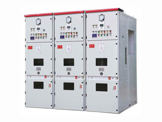
For medium-voltage switchgear configurations, provide the single-line diagram, operating philosophy, local and remote command requirements, and existing interpanel interfaces.
Use the project enquiry page to request the proposed cause-and-effect schedule with the KYN28-12 panel or other suitable configuration. Final interlocking provisions and applicable documentation need technical confirmation for the project.