Identify the voltage each device needs
A voltmeter, an energy meter and a protection relay may require different voltage quantities. One may use phase-to-phase measurements, another phase-to-neutral inputs, and an earth-fault function may need a residual voltage signal. Establish the scheme before selecting the voltage transformer arrangement.
Record the primary connection and every secondary winding's purpose. Avoid treating a voltage presence indicator as a substitute for a VT suitable for metering or protection. The selected equipment must provide the required input characteristics and accuracy under the stated conditions.
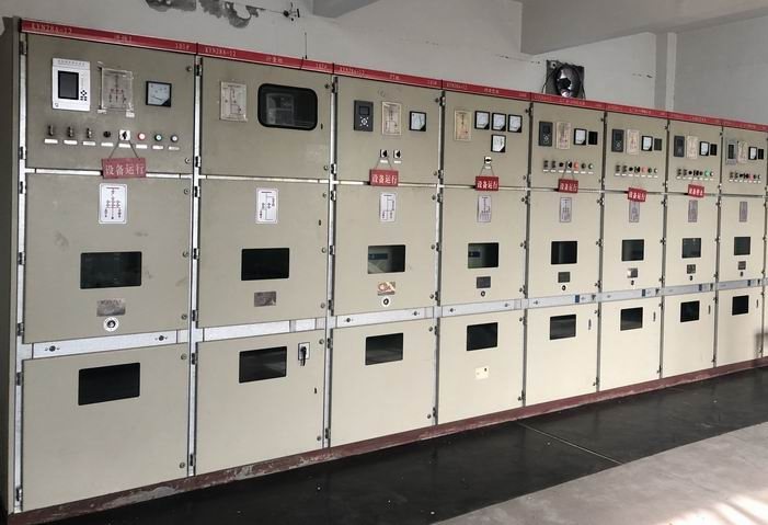
This discussion concerns VTs integrated into a switchgear or RMU assembly. It does not advertise standalone VT supply.
Complete the winding schedule
| Specification | What to record | Why it matters |
|---|---|---|
| Primary voltage and connection | Phase-to-phase or phase-to-earth basis | Prevents a ratio being interpreted against the wrong quantity |
| Secondary voltage | Required value for each instrument circuit | Must match the connected device inputs |
| Winding purpose | Measurement, protection or residual voltage | Determines the relevant performance requirement |
| Accuracy and burden | Class and connected circuit loading | Establishes whether the complete circuit meets its duty |
| Voltage factor and duration | Requirement associated with system earthing and faults | Defines operation under the relevant overvoltage condition |
| Installation arrangement | Fixed or withdrawable construction, protection and access | Affects the assembled panel and maintenance provisions |
Request the exact winding data rather than one combined VA figure that leaves allocation between circuits unclear.
Example: an incomplete ratio statement
An enquiry that says “11 kV to 110 V” can be ambiguous if the required scheme actually uses single-phase VTs connected phase-to-earth. An illustrative specification of 11 kV/√3 to 110 V/√3 states different winding voltage quantities from an unqualified phase-to-phase description.
Neither is a universal default. The approved scheme and instrument inputs determine the correct expression. Include a connection diagram so the quotation reviewer does not have to infer whether the stated values refer to a winding or a three-phase system quantity.
Check the secondary circuit, not only the nameplate
List the burden of each connected instrument and account for the secondary wiring. If a later change adds another meter or lengthens the wiring to a remote panel, reassess the circuit against the proposed VT performance.
Also coordinate secondary protection and the response to loss of the voltage signal. A relay may need to distinguish a genuine system undervoltage from an interruption in its measurement circuit. The scheme designer should define the response and its test method, rather than leaving it to a default setting.
Review the earthing-related application
The neutral arrangement and expected earth-fault clearing behavior influence the required voltage factor. Some VT and network combinations also require consideration of ferroresonance. These are application decisions for the actual system.
Where residual windings or damping measures are proposed, request the manufacturer's approved arrangement and its thermal requirements. Do not apply a generic damping-resistor value from another product manual. VT secondary circuits must not be short-circuited; test and restoration arrangements need the equipment-specific procedure.
For an RFQ, send the single-line diagram, earthing description, required voltage signals, relay and meter data, lead lengths and compartment requirements through project enquiries. Review medium-voltage switchgear or ring main units to identify the assembly. Final VT characteristics and the offered installation require configuration-specific confirmation.