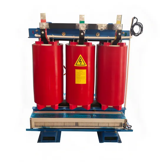
Quick answer
Specify a dry-type transformer temperature package as an interface, not as the word “controller.” The order should identify sensor type and location, controller functions, auxiliary power, fan or cooling outputs, alarm and trip contacts, communication, panel location, wiring, tests and documents. Setpoints and operating responses must follow the approved transformer design and project protection philosophy. If the quotation only says “temperature monitoring included,” the buyer cannot tell which device, contacts or field connections are actually supplied.
Separate temperature sensing from the operating response
A temperature controller normally sits between the transformer’s sensing elements and the equipment or control system that must respond. The sensing arrangement, display, alarm, fan command and trip are different decisions. A project may need local indication only, a remote alarm, staged cooling, a shutdown signal, or a combination. Do not copy a response from another transformer without checking the offered design and the operating duty.
IEC 60076-11:2018 provides the dry-type transformer product context, including thermal and environmental considerations. It does not select a controller, prescribe project setpoints or establish a supplier’s accessory scope. Use the IEC 60076-11 publication together with the approved data sheet and protection philosophy.
| Scope item | Question for the buyer and engineer | Evidence to request |
|---|---|---|
| Sensors | Which winding or temperature points are monitored, and where are they physically installed? | Sensor schedule, wiring diagram and terminal numbers |
| Controller | Is the device local, panel-mounted, door-mounted or inside another cabinet? | Manufacturer, model family, enclosure and arrangement drawing |
| Indication | What must be visible locally, and which values or states are sent remotely? | Display, tag list and communications schedule |
| Alarm and trip | Which conditions create warning, fan start, trip or a latched event? | Cause-and-effect table and approved settings responsibility |
| Cooling output | Are fans or other cooling devices included, and who supplies their power circuit? | Output contact rating, starter or relay boundary and load schedule |
| Auxiliary supply | What AC or DC source, protection and isolation are available? | Single-line diagram, control-power schedule and terminal plan |
| Testing | What is tested at the factory, on site and in the integrated control system? | FAT/SAT procedure, simulated-input method and records |
Specify sensor and controller compatibility
State the sensor technology and the number of points only when the project design supports them. Common arrangements can use winding temperature sensors, resistance temperature detectors or another manufacturer-defined method. The controller input must match the sensor, wiring length, shielding and installation environment. A controller that accepts one sensor type is not automatically interchangeable with a controller using another input.
Request the sensor mounting detail and replacement method. The supplier should show whether sensors are factory installed, brought to a terminal strip, supplied loose or replaced only by an approved service method. Mark cable routes and segregation from power conductors where the project requires it. Keep the sensor tag, winding phase or location and controller channel consistent across the data sheet, drawing, test record and handover file.
Schneider Electric’s dry-type transformer installation guide is a useful manufacturer-specific example of why installation, operation and maintenance information belongs with the equipment documents. Its stated product scope is not a Jinxing configuration or a universal temperature-controller requirement; use it only as a document-format reference. See the Schneider dry-type transformer installation guide.
Make alarms, fans and trips reviewable
Write the operating sequence in plain terms. For each state, identify the input, output, delay or latching behaviour, reset method and receiving system. For example, a warning may remain available to the SCADA system while a fan command is active locally; a separate high-temperature condition may request a controlled shutdown. These are design decisions, not default features of every controller.
Do not place the fan motor, starter, protective device and controller dry contact in one vague line item. Ask who supplies the motor circuit, who provides the auxiliary source, and who terminates the run and status signals. The fan-assisted rating must also be declared separately from the natural-air rating. The existing dry-type transformer temperature monitoring guide discusses sensing and protection choices; this article concentrates on the controller, wiring and supply boundary. The fan-assisted rating guide explains why a fan output does not create an automatic rating increase.
Define power, communication and failure behaviour
Record the nominal control voltage, protective device, isolation point and loss-of-supply alarm. If the controller depends on a separate AC or DC circuit, identify the terminal owner and whether an UPS or battery-backed source is required by the project. State what the controller reports when a sensor is open, shorted, out of range or disconnected. A healthy-looking display cannot substitute for a defined failure indication.
For remote monitoring, specify the protocol or hardwired contacts, point names, quality state and receiving-system owner. A dry contact, pulse, serial gateway and Ethernet device are different deliverables. Do not promise a particular protocol or alarm count until the offered controller and project integration are confirmed.
Example: a factory transformer with optional cooling
Suppose an industrial buyer asks for a dry-type transformer with natural-air operation and optional fans for a defined operating state. The quotation should show the transformer rating in each state, sensor channels, controller location, fan contact or starter, auxiliary source, alarm and trip contacts, and the documents included. If the buyer later asks for a plant-wide communication gateway, the supplier can price the new device and wiring against the original boundary. A revised point list should accompany the change; “remote monitoring added” is not enough for manufacturing release.
Use the Jinxing dry-type transformer range to identify the product family, then send the load profile, environment, control voltage and operating states through the transformer quotation page. Confirm the controller and interface for the offered model. Use the project enquiry page when the schedule and one-line diagram are ready.
RFQ checklist
- Transformer duty, natural-air and any declared forced-cooling operating states.
- Sensor type, location, channel count, wiring and replacement method.
- Controller location, display, enclosure, model evidence and power source.
- Warning, fan, trip, reset, latching and sensor-fault behaviour.
- Fan motor, starter, protective device, terminals and installation responsibility.
- Hardwired contacts, protocol, point names, quality states and receiving system.
- Factory simulation, site loop checks, integrated tests and handover records.
- Explicit exclusions and a revision process for later monitoring requests.
FAQ
Is a temperature controller always included with a dry-type transformer?
No. The quotation must state whether sensors, controller, contacts, fan controls, power supply, wiring and tests are included, supplied loose or excluded.
Can the alarm and trip temperatures be copied from another project?
No. Setpoints and operating responses require review against the offered transformer, sensor arrangement, loading, cooling and protection philosophy. Record who approves the final values.
Does a fan output prove that the transformer has a higher continuous rating?
No. Any fan-assisted rating must be declared with its conditions, duration and failure response. A controller contact by itself is not a rating statement.