Start with the protection objective
The purpose of a feeder relay is to identify defined abnormal conditions and initiate the required action. A long feature list does not show whether the selected device will perform that job in the proposed switchgear.
Describe the protected circuit, possible sources and the network earthing arrangement. An outgoing feeder in a radial network may need a different scheme from a circuit with multiple feeding directions. Earth-fault behavior also changes with system earthing. The protection engineer should determine the required functions from the network study before the panel designer selects the detailed relay hardware.
Build a function-to-interface schedule
| Requirement | Engineering decision | Hardware or configuration evidence |
|---|---|---|
| Phase-fault protection | Time grading and required instantaneous behavior | Suitable current inputs and available setting ranges |
| Earth-fault protection | Sensitivity and directional requirement | Residual or core-balance input and any required voltage reference |
| Transformer-specific signals | Alarm versus trip for each accessory | Input count, contact characteristics and logic assignment |
| Breaker control | Trip, close and supervision responsibilities | Output duties and approved circuit design |
| Remote monitoring | Required events and operational data | Protocol, physical ports and licensed options |
| Event investigation | Records needed after a trip | Time synchronization and retrievable event data |
The schedule should identify the exact order code. A feature available somewhere in a relay family may depend on an input module, firmware option or license that is absent from the proposed device.
Example: the missing voltage input
Suppose a proposal lists directional protection as a feature, but its chosen hardware variant has only the current inputs intended for a simpler scheme. Before approval, ask how the required directional element obtains its polarizing quantity and whether the relevant inputs and function are actually included.
Do not resolve the discrepancy by assuming every directional element uses the same method. Obtain the selected relay's application documentation and have the protection engineer confirm the intended scheme. The useful acceptance item is a documented function with all required inputs, not a tick beside a catalogue feature.
Separate settings from panel supply
A panel can be correctly wired while carrying provisional relay settings. The quotation should state who provides the protection study, who approves settings, who loads the configuration and who proves the trip chain at commissioning.
Require a final settings file tied to the relay identity and drawing revision. Record any distinction between factory demonstration settings and the approved site settings. This prevents an apparently complete factory test from concealing an unfinished engineering responsibility.
Review integration and replacement constraints
For an existing lineup, compare CT and VT secondary characteristics, auxiliary supply, trip-coil interface, panel cutout and terminal access. A newer relay is not automatically a drop-in replacement even if it performs similar functions.
Communications should be reviewed with equal care. Identify which points the owner needs and how they are mapped, timestamped and tested. A compatible protocol name does not establish that the final integration is complete. Include the agreed communications checks and their responsible parties in the documented switchgear commissioning scope.
RFQ inputs for the assembled panel
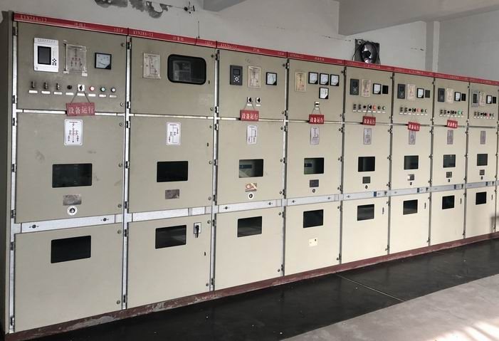
Send the single-line diagram, earthing description, fault study, protection function schedule, CT/VT information, auxiliary supply and approved device requirements through project enquiries. Start with medium-voltage switchgear to define the assembly. Relay descriptions here refer to configured panel components and do not establish standalone supply, a particular relay brand or completed protection-setting services.